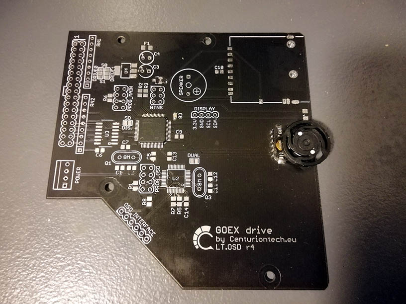
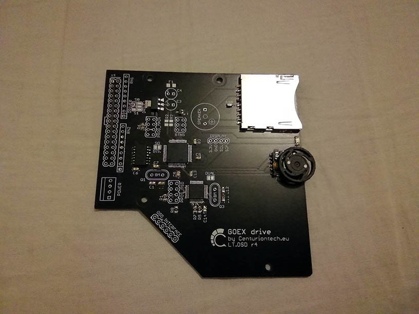
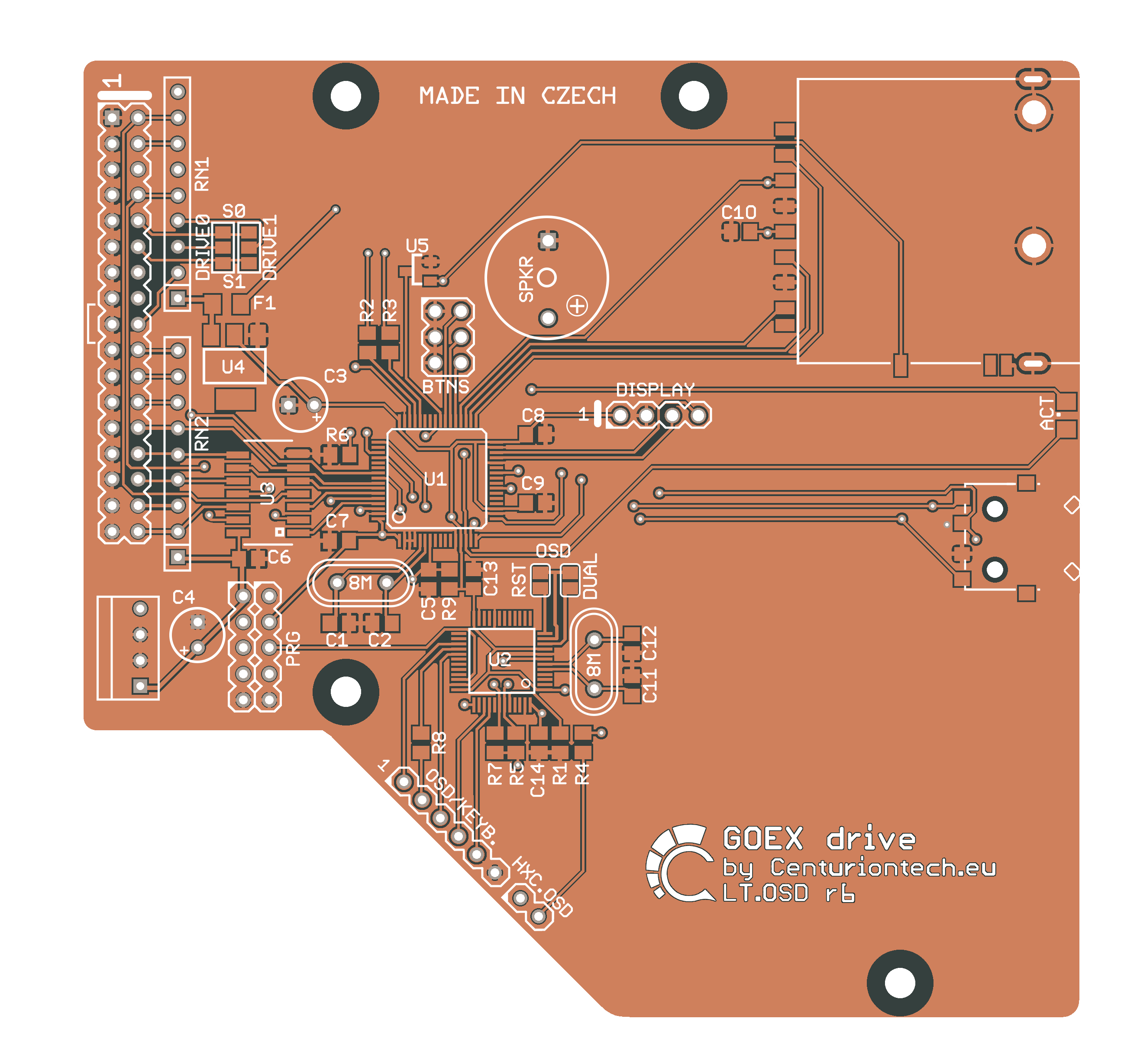
GOEX r4 & r6
24/02/2021 [All informations done here are tested well]


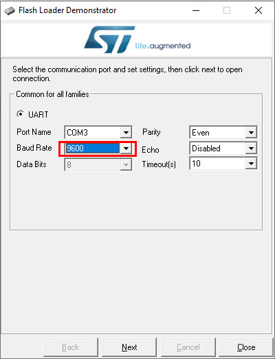
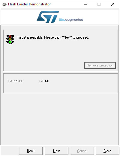
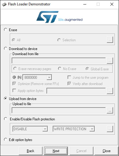
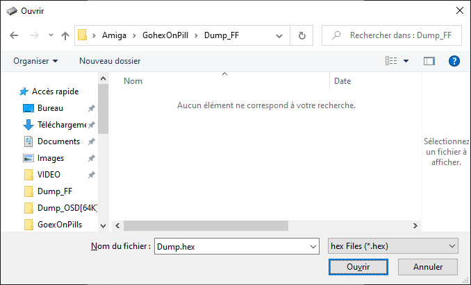
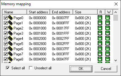
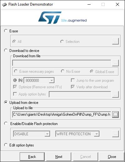
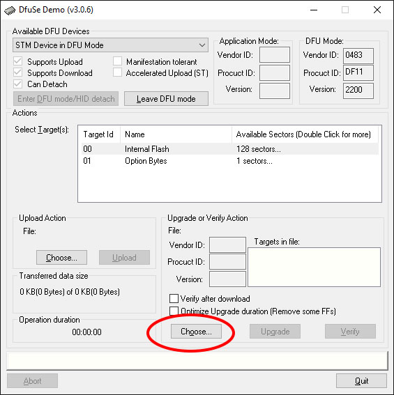
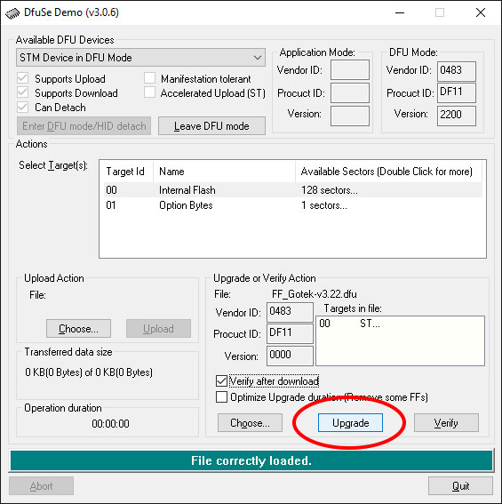
Check all Page is selected and so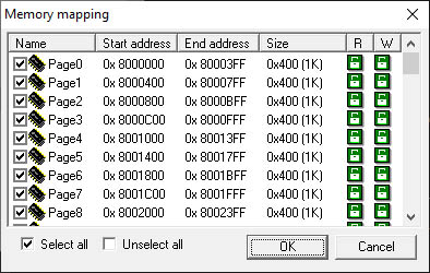 |
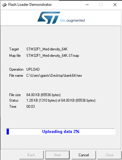
Validate it by clicking on OK And then, finaly, clik to NEXT to start the Dump.  |


|
cat Dump.hex |egrep -v "^:02000004|^:020000020000F" |while read LINE; do echo "${LINE}" |cut -c10-73 >> Dump.txt ; done cat Dump.txt |tr -d "\n" > DumpOSD.map ; xxd -r -p DumpOSD.map DumpOSD.bin |
|
dd if=DumpOSD.bin of=DumpOSD.bin.cut bs=13276 count=1 |
|
root:/tmp# crc32 DumpOSD.bin.cut a7c41962 root:/tmp# crc32 FF_OSD-v1.8.bin a7c41962 root:/tmp# diff -qs DumpOSD.bin.cut DumpOSD.bin.cut Files DumpOSD.bin.cut and DumpOSD.bin.cut are identical |

 |  |


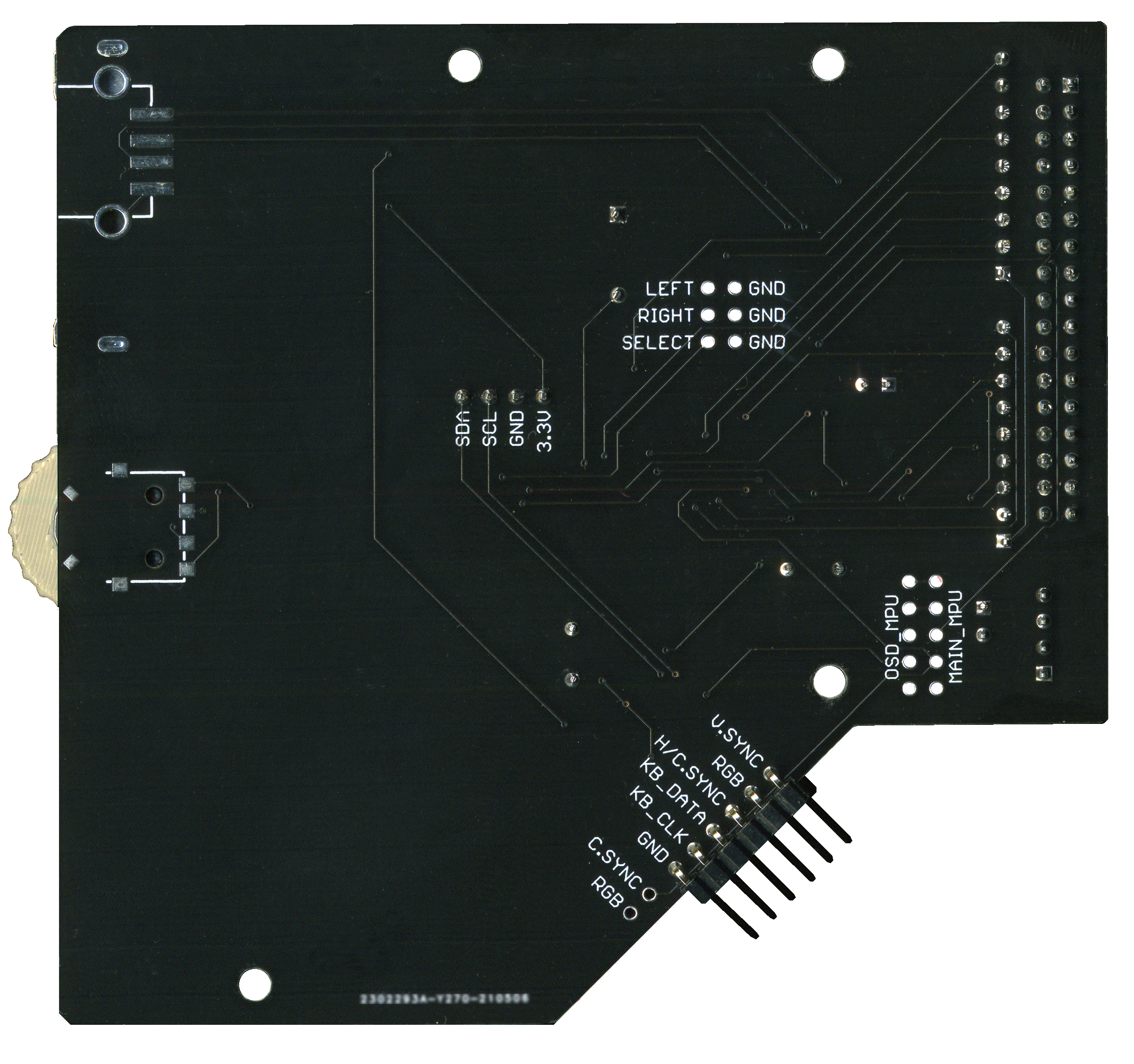
| Sync Polarity | [Low|High|Auto] | |
| Pixel Timing | [15kHz|VGA|Auto] | |
| Display Height | [Normal|Double] | |
| Display Output | [PB15/SPI2|PA7/SPI1] | |
| Display Enable | [None|PA15 Act.HIGH|PA15 Act.LOW] | |
| H.Off (1-199) | [1->199] | 175 goes out of the display' |
| V.Off (1-299) | [1->200] | |
| Save New Config? | [Save+Reset|Use|Discard|Factory Reset|Save] | We can use here the 'Factory Reset' if we made a mistake' |
| = Prev | |
| = Next | |
| = Select | |
| = Toggle OSD On/Off | |
| = Steals the keyboard |

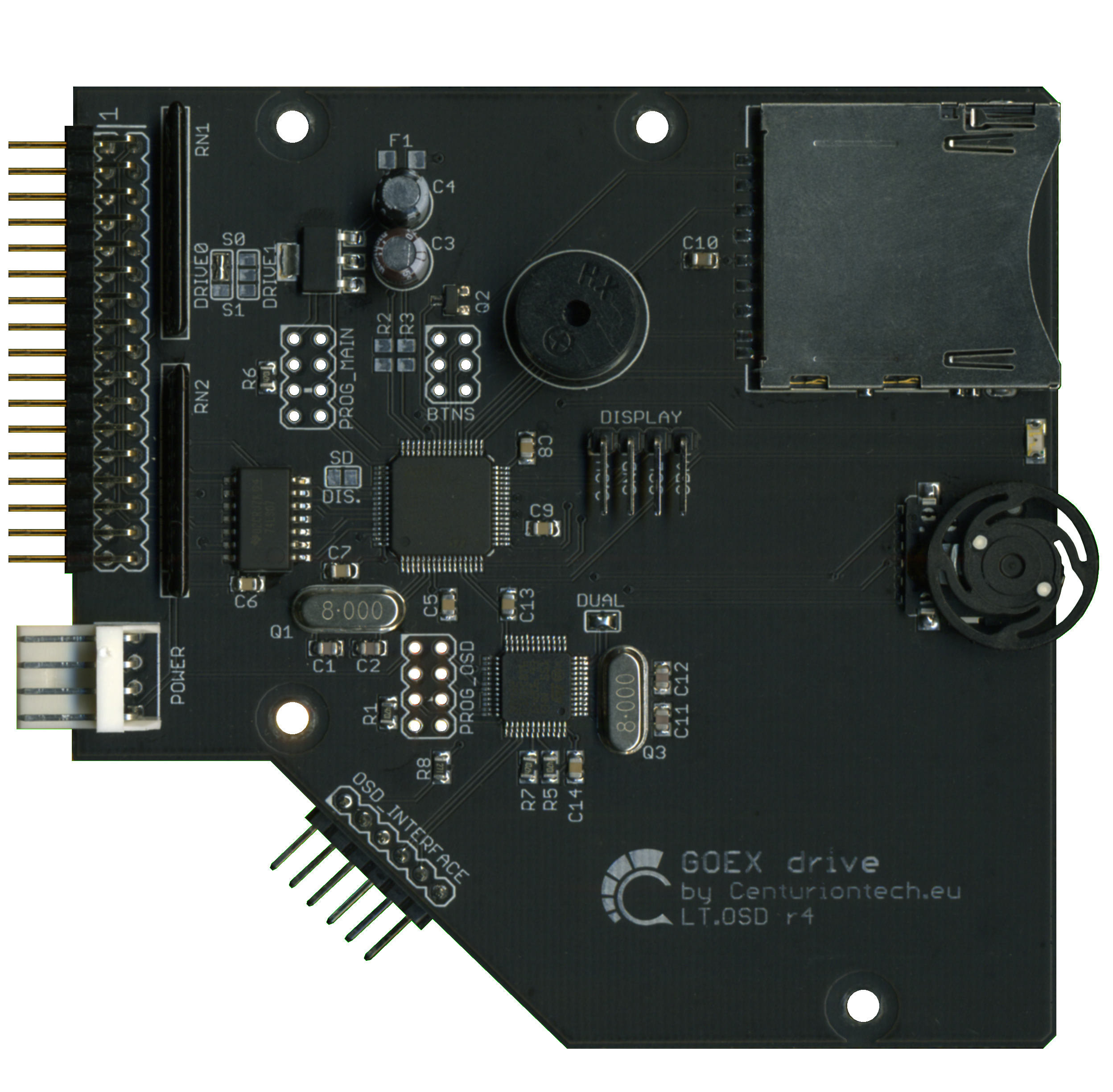
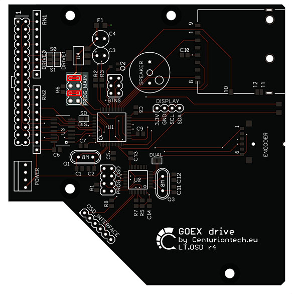
| C4 | 22 uF 10V Radial capacitor électrolytic polarised |
| C3 | 10 uF 16V Radial capacitor électrolytic polarised |
| C1,C2,C11,C12 | 22 pF SMD 805 ceramic |
| C10 | 1uF SMD 0805 ceramic |
| C5,C6,C7,C8,C9,C13,C14 | 100 nF SMD 805 ceramic |
| R1 | 4,7 Kohm SMD 805 |
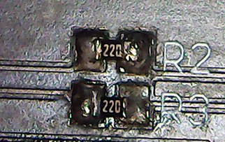
| R2,R3 | 22 ohm SMD 805 [optional] |
| R5,R6,R7 | 4,7 Kohm SMD 805 |
| R8 | 270 ohm SMD 805 |
| RN1,RN2 | 9A102G DIP exclusion 9pin 1K |
| RN2 | 9A102G DIP exclusion 9pin 1K |
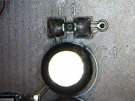
| F1 | 0 ohm SMD 805 [Optional] |
| Q1,Q3 | Cristal Quartz 8Mhz |
| Q2 | 2N7002 MOFSET SMD |
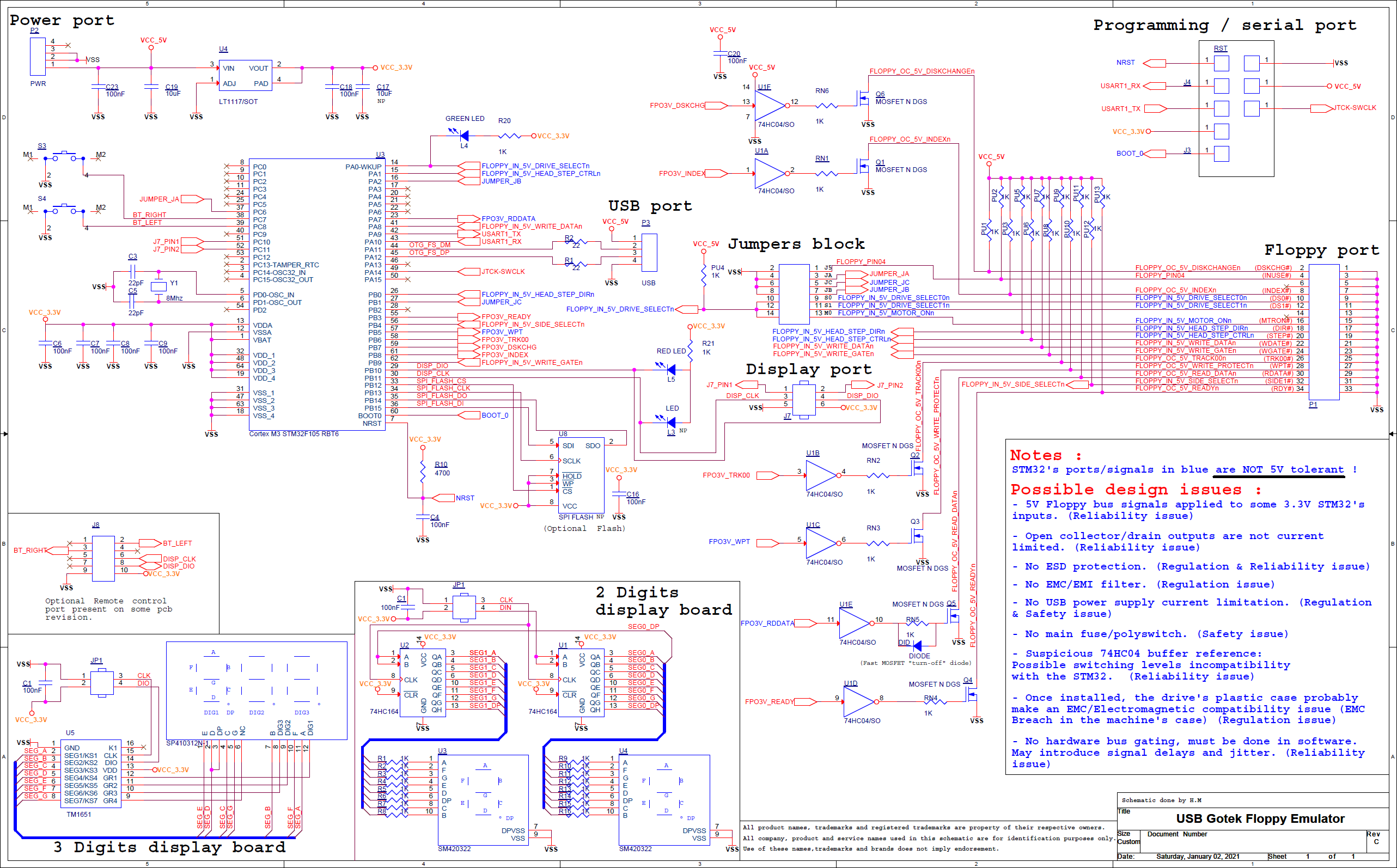
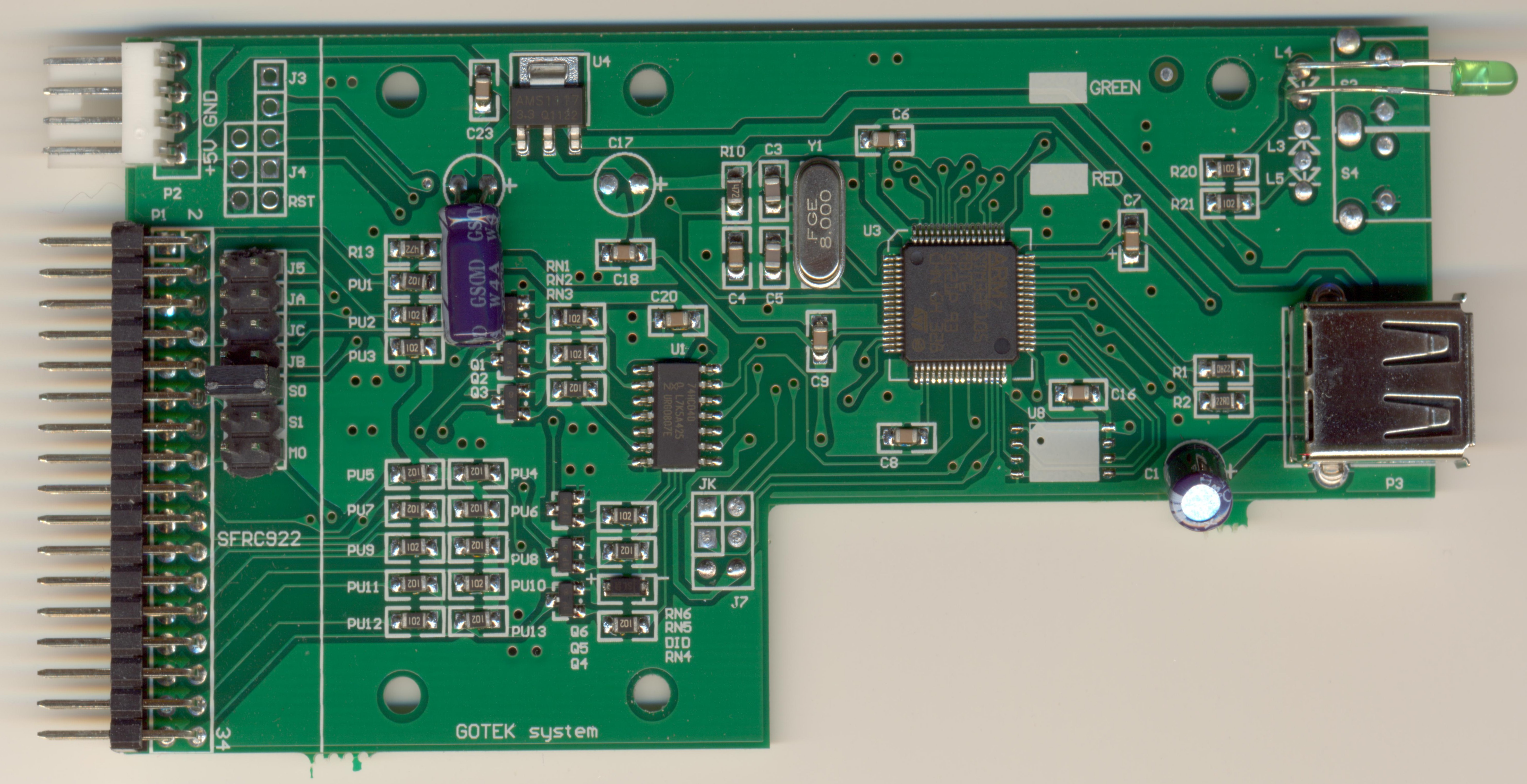
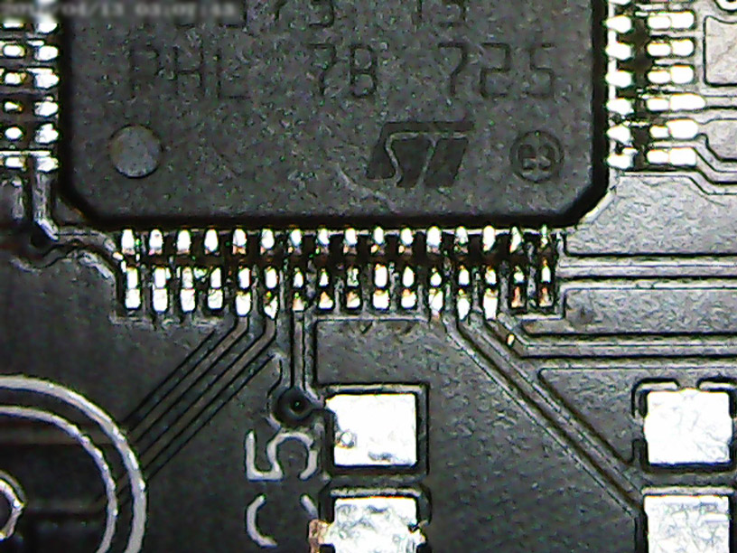
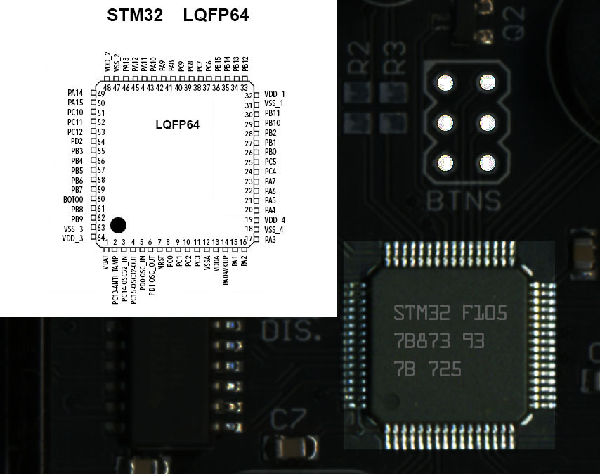
| U1 | STM32F105RBT6 7B873 93 PHL 7B 725 [SMD LQFP-64] |
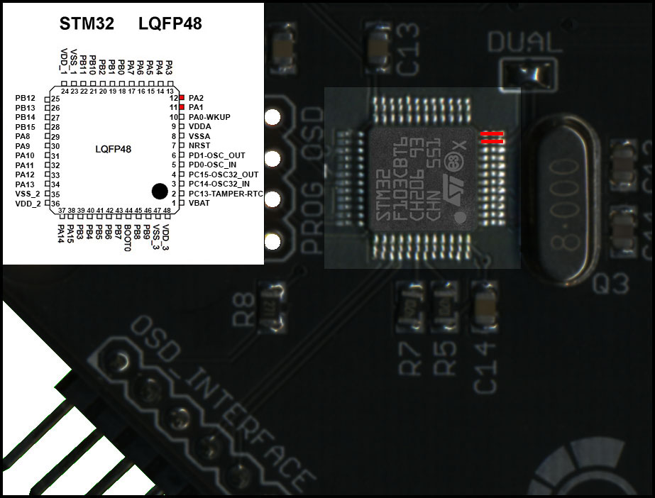
| U2 | STM32F103C8T6 GH206 93 CHN 551 [SMD LQFP-48] |
| U3 | 74LS07 SMD SOP14 |
| U4 | 3.3V Regulator GH27G (or 1117) |


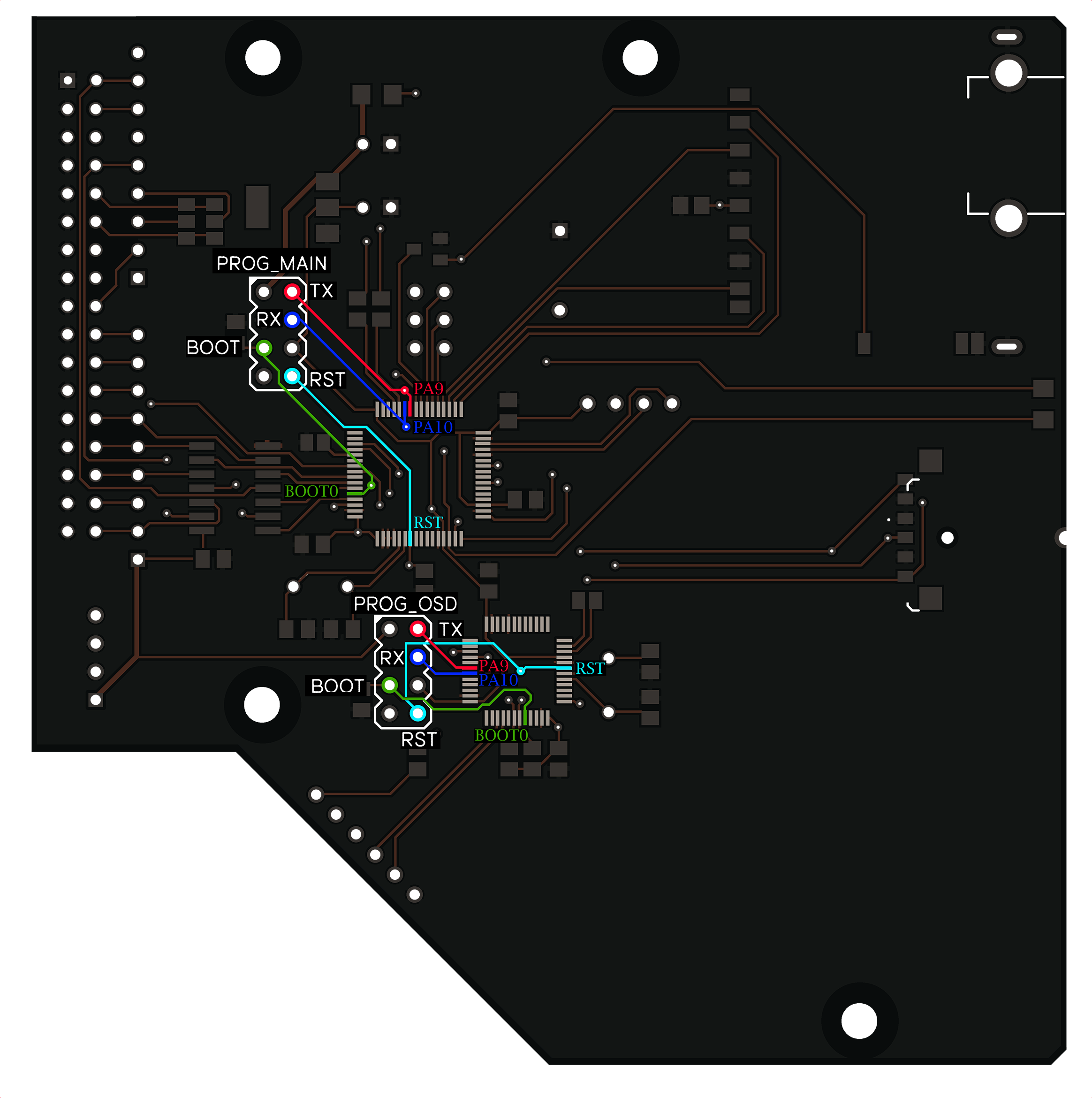
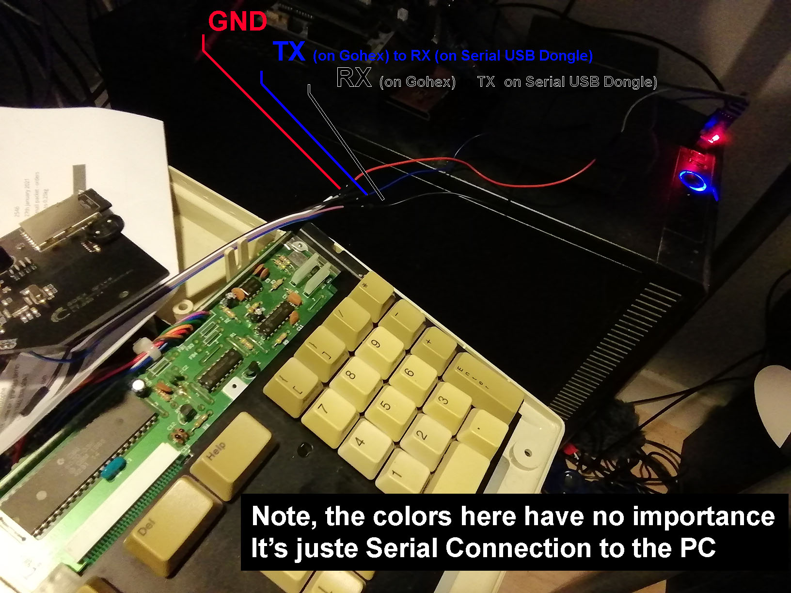
| ID | SIGNAL | GOTEK | GOTEK |
|---|---|---|---|
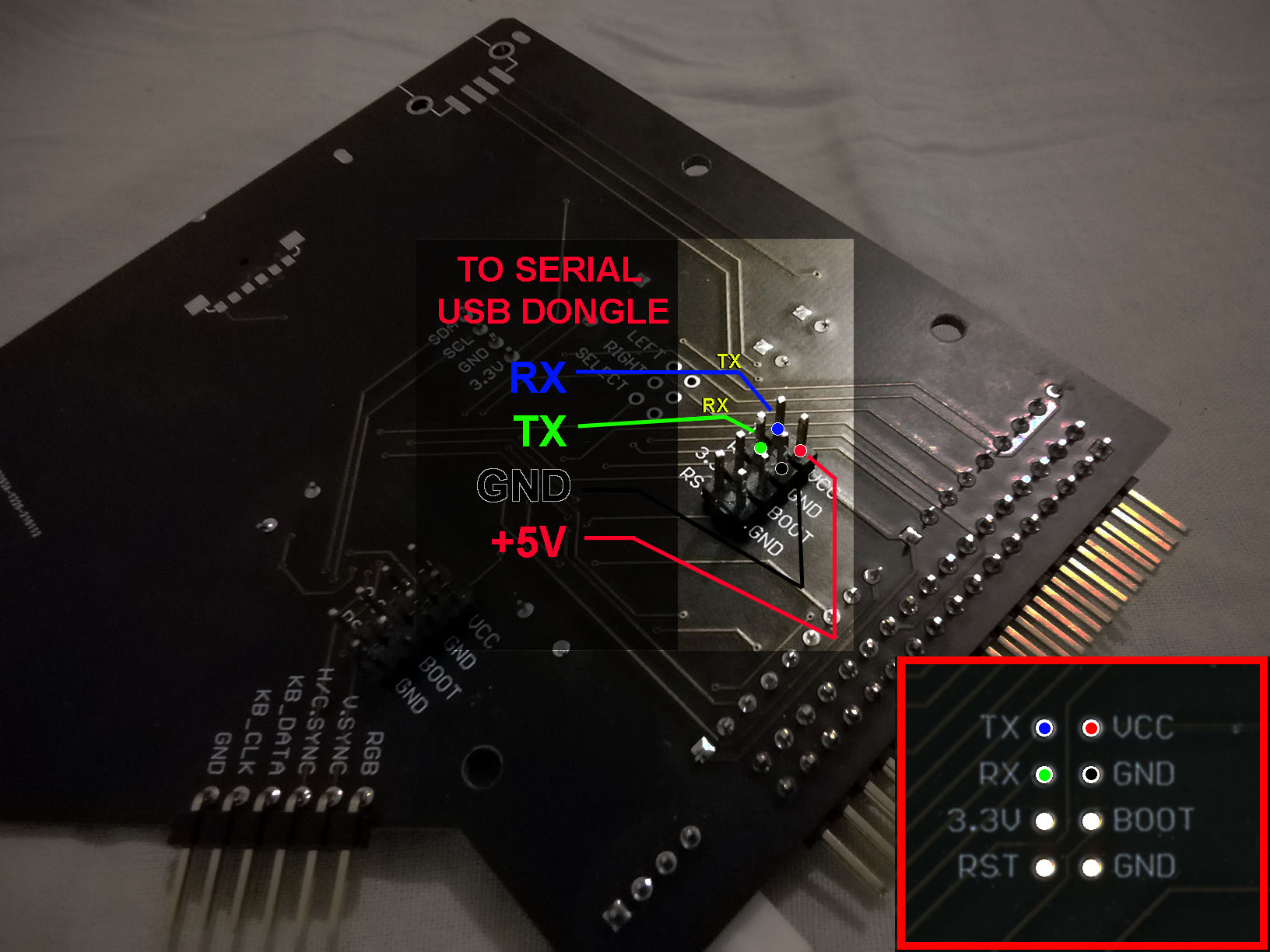
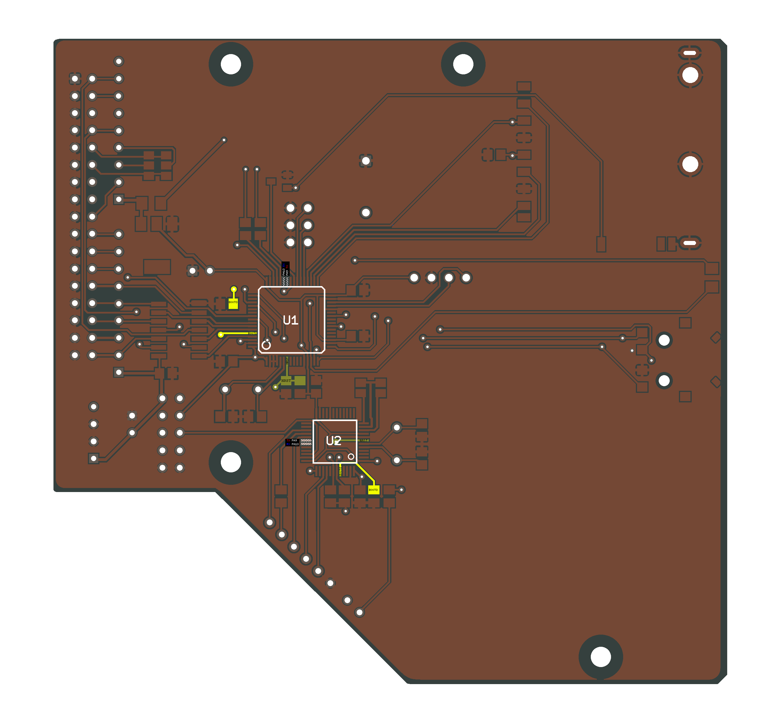
| PROG MAIN (ak FF) | TX | PIN 49 (PA9) | USART1_TX (PIN 49) |
| RX | PIN 43 (PA10) | USART1_RX PIN(43) | |
| RST | PIN 7 (NRST) | NRST (PIN 7) | |
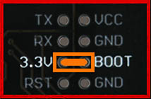
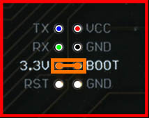
| BOOT0 | PIN 60 (BOOT0) | BOOT_0 J3 (PIN 60) |


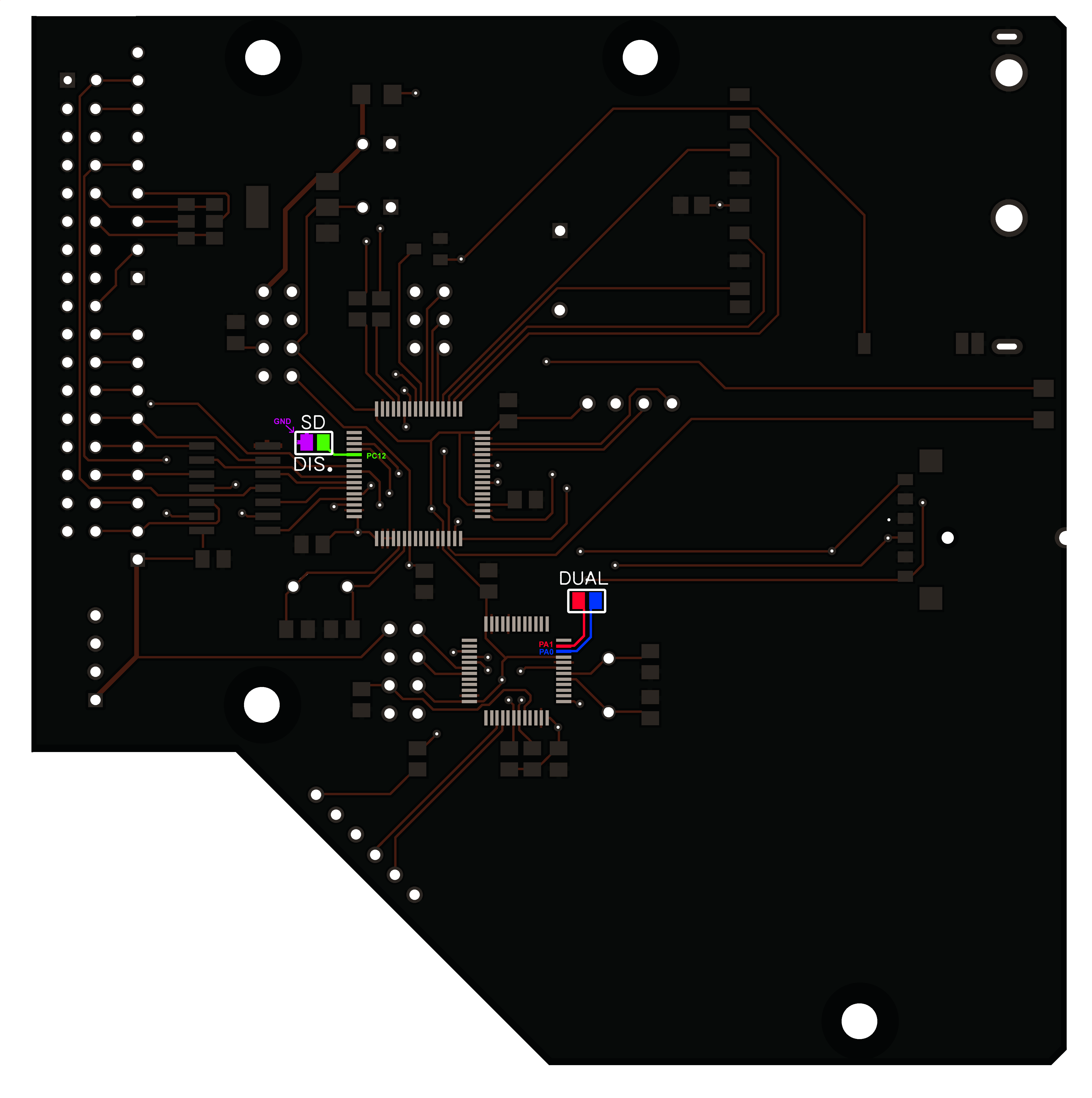
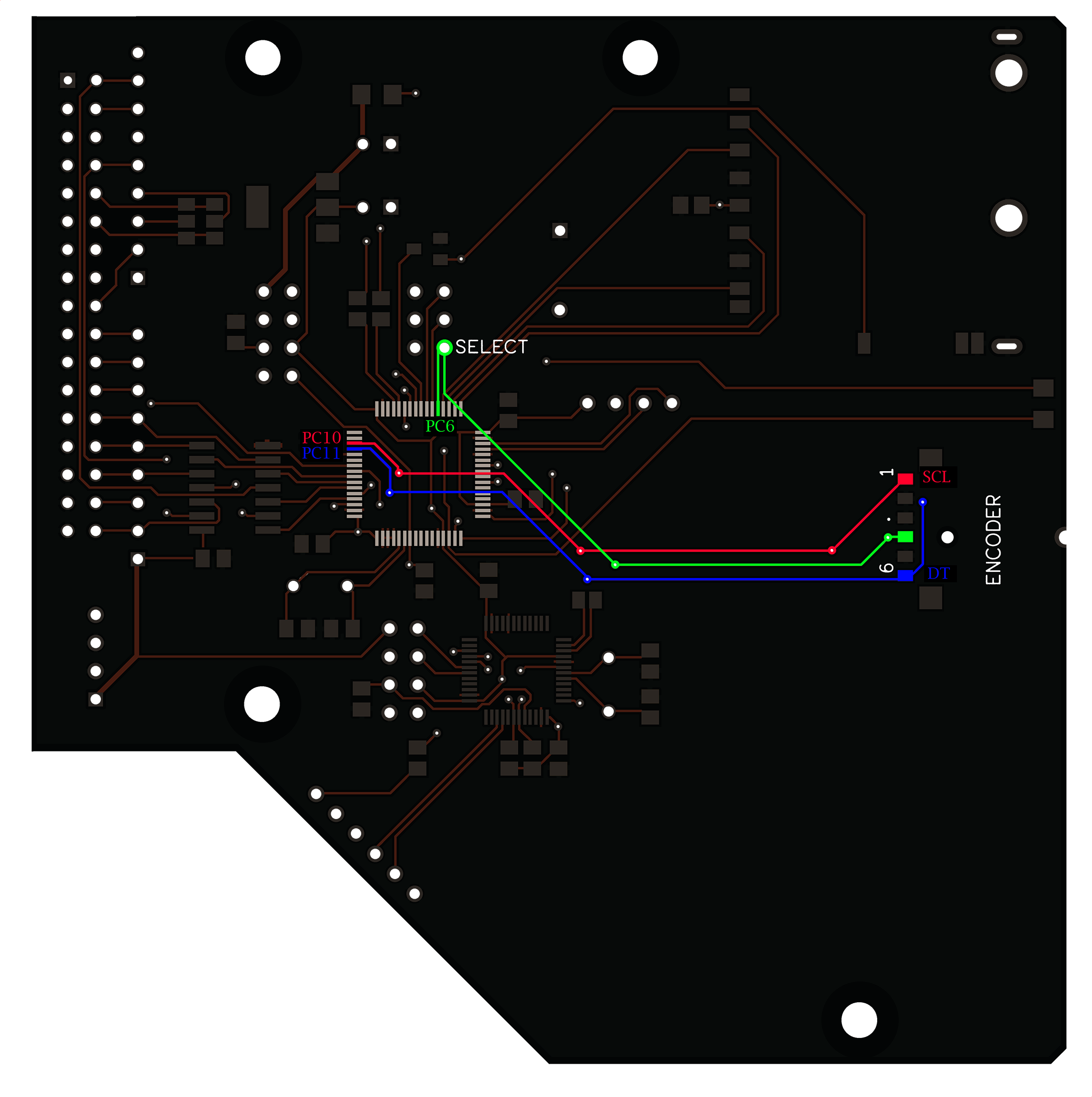
| SIGNAL | On Goex | On Gotek | SELECT | PC6_Pin37 | JUMPER_JA (STM32=Pin37) | DT | PC6_Pin52 | J7_Pin1 (STM32=Pin37) | CLK | PC6_Pin51 | J7_Pin2 (STM32=Pin37) |
|---|


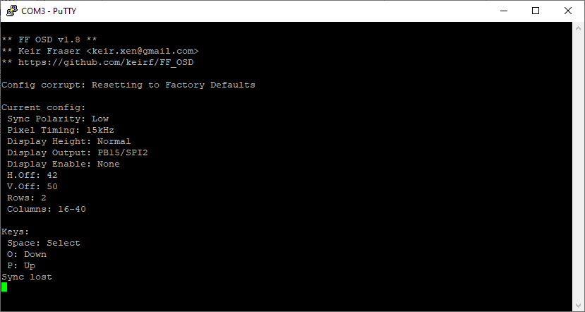
| Jumpered: Resetting to Factory Defaults |
|---|
| If you accidentally Save a bad configuration, you can reset to Factory Defaults by placing a jumper across A1-A2 and reset or power cycle FF OSD |
| ACTION | DISPLAY CONFIGURATION | DEFAULT VALUE |
|---|---|---|
| PUSH_BUTTON | **Main Menu** | |
| ROTARY_UP | Exit | |
| ROTARY_UP | Configure FF OSD | |
| PUSH_BUTTON | Confirm OSD Cnf? | |
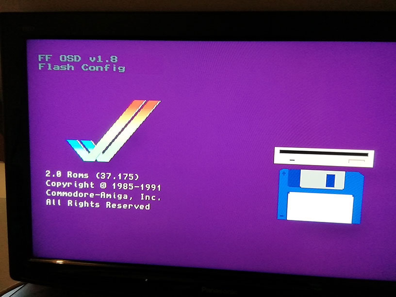
| PUSH_BUTTON | Flash Config | |
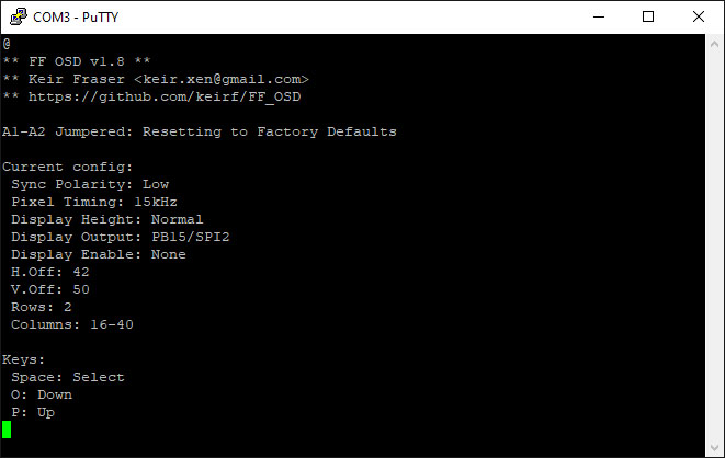
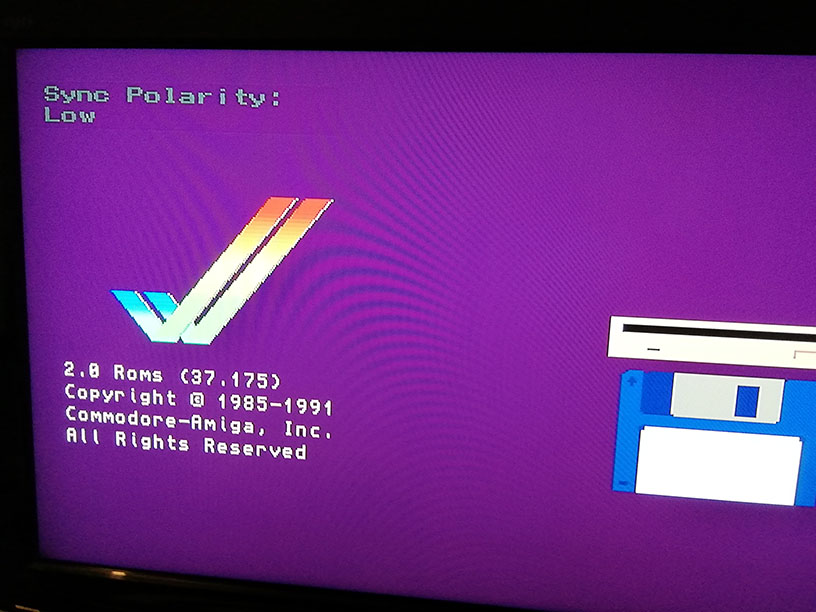
| PUSH_BUTTON | Sync Polarity | Low |
| PUSH_BUTTON | Pixel Timing | 15Khz |
| PUSH_BUTTON | Display Height | normal |
| PUSH_BUTTON | Display Output | PB15/SPI2 |
| PUSH_BUTTON | Display Enable | None |
| PUSH_BUTTON | H.Off | 42 |
| PUSH_BUTTON | V.Off | 50 |
| PUSH_BUTTON | Save New Config ? | save |
| ROTARY_UP | Factory Reset | |
| PUSH_BUTTON | [AMIGA_REBOOT] |


| C3,C4 | 22 uF 35V Radial capacitor électrolytic polarised |
| C5,C6,C7,C8,C9,C13,C14 | 100 nF SMD 805 ceramic |
| C1,C2,C11,C12 | 22 pF SMD 805 ceramic |
| C10 | 1uF SMD 0805 ceramic |
| R6,R9 | 10 Kohm SMD 805 |
| R4,R8 | 270 ohm SMD 805 |
| R1,R5,R7 | 4,7 Kohm SMD 805 |
| RN1,RN2 | 9A102G DIP exclusion 9pin 1K |
| Q1,Q2 | Cristal Quartz 8Mhz SMD |
| U1 | AT32F415RBT7 [SMD LQFP-64] |
| U2 | CKS32F103C8T6 [SMD LQFP-48] |
| U3 | 74LS07 SMD SOP14 |
| U4 | 3.3V Regulator GH27G (or 1117) |
| U5 | 2N7002 MOFSET SMD |
| F1 | 0 ohm SMD 805 [Optional] |